
Original Line Electric® Actuator
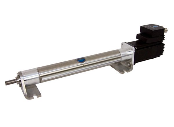 The Bimba Original Line Electric actuator is designed, built, and tested to provide the longest life, greatest durability, highest speed, and greatest thrust per dollar. They are ideal for applications requiring greater control for enhanced flexibility. Many mounting, motor, performance, and custom options are available to suit your application needs.
- Bore sizes/Thrust ranges: 1.5″/up to 75 lbs., 2″/up to 150 lbs., 3″/up to 350 lbs.
- Non-rotating rod is standard with Original Line Electric® Actuator
- Choose no motor, AC or DC stepper motors
- Motor, encoder, and driver available out of the box
- The reverse parallel motor option conserves space
- Screw accuracy: 0.0006 in./in.
How to OrderThe model number of all Original Line Electric® Actuators consists of alphanumeric clusters designating product type, body size (number designates maximum thrust capacity in pounds), stroke length, lead, mounting style, motor type and configuration, and options. The example below describes OLE-7512.12-50BF-T1Y2, a 75 pound maximum thrust model with 1.5 inch diameter body, 12.12 inch stroke, 0.50 inch lead, block front mount, switch track, 23 frame stepper motor with encoder, and driver. Piston magnets are included.
|
|
|
|
||||||||||||||||||||||||||||||||||
![]()
![]()
![]()
![]()
![]()
![]()
![]()
![]()
![]()
![]()
![]()
| OLE | – | 75 | 12.12 | – | 50 | BF | – | T1Y2 | ||||||||||||||||||||
|
|
||||||||||||||||||||||||||||||||||||||||||||
|
|
||||||||||||||||||||||||||||||||||||||||||||
|
|||||||||||||||||||||||||||||||||||||||||||||
No Motor Option (N)
| Base Part Number | Lead2 (Inches) |
Backlash3 (Inches) |
Screw Accuracy (in./in.) |
Screw Repeatability (micro inches) |
Maximum Load (lbs.) |
Actuator Inertia Adder (oz-in2) |
Actuator Inertia per inch (oz-in2)4 |
|---|---|---|---|---|---|---|---|
| OLE-75-xx-12xx-Nx1 | .125 | .003 | 0.0006 | 50 | 75 | .003 | .006 |
| OLE-75-xx-50xx-Nx | .50 | .005 | 0.0006 | 50 | 75 | .003 | .006 |
| OLE-75-xx-75xx-Nx | .75 | .007 | 0.0006 | 50 | 75 | .003 | .006 |
| OLE-150-xx-16xx-Nx1 | .16 | .005 | 0.0006 | 50 | 150 | .218 | .021 |
| OLE-150-xx-25xx-Nx | .25 | .006 | 0.0006 | 50 | 150 | .218 | .021 |
| OLE-150-xx-50xx-Nx | .50 | .008 | 0.0006 | 50 | 150 | .218 | .021 |
| OLE-350-xx-20xx-Nx1 | .20 | .003 | 0.0006 | 50 | 350 | 1.588 | .103 |
| OLE-350-xx-50xx-Nx | .75 | .005 | 0.0006 | 50 | 350 | 1.588 | .103 |
| OLE-350-xx-100xx-Nx | 1.0 | .007 | 0.0006 | 50 | 350 | 1.588 | .103 |
| Operating Temperature Range: -20º F to 160º F (-29º C to 71º C) Standard IP rating: None Maximum stroke: 18 inches RoHS compliant |
|||||||
| 1Self-locking threads 2Inches per revolution of screw 3Amount of end play on screw. Low backlash designs are available. Contact technical Support. 4Inertia is given per inch of stroke |
|||||||
Step Motor and Motor/Driver Options (P, E, Y, Z)
| Base Part Number | Lead2 (Inches) |
Backlash3 (Inches) |
Screw Accuracy (in./in.) |
Screw Repeatability (micro inches) |
Actuator Inertia Adder (oz-in2) |
Actuator Inertia per inch (oz-in2)4 |
Motor Inertia Adder (oz-in2)5 |
Maximum Current Draw4 |
|---|---|---|---|---|---|---|---|---|
| OLE-75-xx-12xx-P11 | .125 | .003 | 0.0006 | 50 | .003 | .006 | .44 | 1.7 |
| OLE-75-xx-50xx-P1 | .50 | .005 | 0.0006 | 50 | .003 | .006 | .44 | 1.7 |
| OLE-75-xx-75xx-P1 | .75 | .007 | 0.0006 | 50 | .003 | .006 | .44 | 1.7 |
| OLE-75-xx-12xx-P21 | .125 | .003 | 0.0006 | 50 | .003 | .006 | 2.51 | 4.24 |
| OLE-75-xx-50xx-P2 | .50 | .005 | 0.0006 | 50 | .003 | .006 | 2.51 | 4.24 |
| OLE-75-xx-75xx-P2 | .75 | .007 | 0.0006 | 50 | .003 | .006 | 2.51 | 4.24 |
| OLE-150-xx-16xx-P21 | .16 | .005 | 0.0006 | 50 | .218 | .021 | 2.51 | 4.24 |
| OLE-150-xx-25xx-P2 | .25 | .006 | 0.0006 | 50 | .218 | .021 | 2.51 | 4.24 |
| OLE-150-xx-50xx-P2 | .50 | .008 | 0.0006 | 50 | .218 | .021 | 2.51 | 4.24 |
| OLE-350-xx-20xx-P31 | .20 | .003 | 0.0006 | 50 | 1.588 | .103 | 15.03 | 5.6 |
| OLE-350-xx-50xx-P3 | .75 | .005 | 0.0006 | 50 | 1.588 | .103 | 15.03 | 5.6 |
| OLE-350-xx-100xx-P3 | 1.0 | .007 | 0.0006 | 50 | 1.588 | .103 | 15.03 | 5.6 |
| Operating Temperature Range: 32º F to 122º F (0º C to 50º C) If the driver is remotely mounted and protected from head, maximum operating temperature will be 160º F (71º C). Maximum stroke: 18 inches RoHS compliant |
||||||||
| 1Self-locking threads 2Inches per revolution of screw 3Amount of end play on screw 4Inertia is given per inch of stroke 5Inertia for motor by itself 6For driver sizing for actuators supplied without drivers |
||||||||
Reverse Parallel Motor Options (R, S, Q & P, E, Y, Z)
| Base Part Number | Lead2 (Inches) |
Backlash3 (Inches) |
Screw Accuracy (in./in.) |
Screw Repeatability (micro inches) |
Actuator Inertia Adder (oz-in2) |
Actuator Inertia per inch (oz-in2)4 |
Motor Inertia Adder (oz-in2)5 |
Maximum Current Draw4 |
|---|---|---|---|---|---|---|---|---|
| OLE75-xx-12Rx-P11 | .125 | .003 | 0.0006 | 50 | .096 | .006 | .44 | 1.7 |
| OLE75-xx-50Rx-P1 | .50 | .005 | 0.0006 | 50 | .096 | .006 | .44 | 1.7 |
| OLE75-xx-75Rx-P1 | .75 | .007 | 0.0006 | 50 | .096 | .006 | .44 | 1.7 |
| OLE-5-xx-12Rx-P21 | .125 | .003 | 0.0006 | 50 | .096 | .006 | 2.51 | 4.24 |
| OLE75-xx-50Rx-P2 | .50 | .005 | 0.0006 | 50 | .096 | .006 | 2.51 | 4.24 |
| OLE75-xx-75Rx-P2 | .75 | .007 | 0.0006 | 50 | .096 | .006 | 2.51 | 4.24 |
| OLE150-xx-16Rx-P21 | .16 | .005 | 0.0006 | 50 | 1.01 | .021 | 2.51 | 4.24 |
| OLE150-xx-25Rx-P2 | .25 | .006 | 0.0006 | 50 | 1.01 | .021 | 2.51 | 4.24 |
| OLE150-xx-50Rx-P2 | .50 | .008 | 0.0006 | 50 | 1.01 | .021 | 2.51 | 4.24 |
| OLE350-xx-20Rx-P31 | .20 | .003 | 0.0006 | 50 | 9.51 | .103 | 15.03 | 5.6 |
| OLE350-xx-50Rx-P3 | .75 | .005 | 0.0006 | 50 | 9.51 | .103 | 15.03 | 5.6 |
| OLE350-xx-100Rx-P3 | 1.0 | .007 | 0.0006 | 50 | 9.51 | .103 | 15.03 | 5.6 |
| Operating Temperature Range: 32º F to 122º F (0º C to 50º C) If the driver is remotely mounted and protected from head, maximum operating temperature will be 158º F (70º C). Maximum stroke: 18 inches RoHS compliant |
||||||||
| 1Self-locking threads 2Inches per revolution of screw 3Amount of end play on screw 4Inertia is given per inch of stroke 5Inertia for motor by itself 6For driver sizing for actuators supplied without drivers |
||||||||
Model DRV Specifications
| Amplifier | Digital MOSFET. 20 kHz PWM. Suitable for driving two phase and four pahse step motors with four, six or eight leads. |
| Supply voltage: | |
| DRV-4 24-48 VDC Under voltage alarm: 20 VDC Over voltage shutdown: 60VDC DRV-8 24-75 VDC Under voltage alarm: 20 VDC Over voltage shutdown: 85VDC |
|
| Motor current: | |
| 0.5 to 7.8 amps/phase peak of sine (DRV8) 0.25 to 4.5 amps/phase peak of sine (DRV4) |
|
| Digital Inputs | Optically isolated, 5 – 24V logic. Sourcing, sinking or differential signals can be used. Minimum “on” voltage: 4 VDC. Maximum voltage: 30 VDC Input current: 5 mA typ at 4V, 15 mA typ at 30V. |
| Fault Output | Photodarlington, 80 mA, 30 VDC max. Voltage drop: 1.2V max at 80 mA. |
| Physical | 1.3 x 3.0 x 4.65 inches (33 x 75.5 x 118 mm) overall. 10.8 oz (305 g) including mating connectors. Ambient Temperature Range: 0º C to 50º C (32º F to 122º F). |
 Original Line Electric